Tech Stuff - USB and Firewire
USB (1.x, 2.0 and the significantly different (but compatible) 3.0)and FireWire (IEEE 1394a and b) were adopted for serial communications because they reduce PC connection size/costs and improve performance. Modern Monitor/Display interfaces, such as HDMI, DisplayPort and Thunderbolt, are very fast pure serial interfaces.
The 'On-the-Go (OTG)' specification introduced a Mini-B connector, Micro A and B connectors (in 2007) as well as peer-to-peer operation.
USB 3.2 introduced the USB Type C (USB-C) connector which seems destined to replace both the standard and micro USB connectors. It has a smaller footprint than the standard USB (USB-A), is slightly bigger than the micro USB, allows a increased current (5A vs 3A) but has the overriding merit of having no physical connection polarity. No more muscle-bound users trying to force upside down micro USB connectors against all the evidence.
Great to see that the USB folk make their specs freely available unlike the IEEE 1394 folks.
USB (1.x and 2.0)
The USB specification defines what are now called standard A and B type connectors. The A type connects to the Host, Hub or Bridge. The Type B connects to the end peripheral. This is shown in diagram 1 below.
USB 1.x (Full-Speed) provides up to 1.5 M Bit/s (low-bandwidth) at distances of 3m or 12 M Bit/s (Full-Bandwidth) at distances of 5m. Version 2.0 (hi-Speed) supports speeds to 480 M Bit/s at distances of up to 5m. In all cases a maximum of 5 hubs may be supported. USB 3.0 provides up 5.0 GB.
USB (1.x and 2.0) provide a base current of 100 mA and a maximum current of base X 5 = 500 mA for powering of peripherals or battery charging applications. In all cases power is at a nominal 5.0V. USB 3.0 provides up 900 mA.
Note: The Battery Charging Specification (BCS) 1.2 defines increased current capabilities where USB connection are used soley for charging purposes using, say, a Dedicated Charging Port (DCP). BSC 1.2 is compatible with both USB 2.0 and 3.0 connector types.
Standard Type A Pin assignment
 |
| Pin |
Name |
Color |
Notes |
| 1 |
VBUS |
Red |
Power. Nominal 5.0V |
| 2 |
D- |
White |
Data - |
| 3 |
D+ |
Green |
Data + |
| 4 |
GND |
Black |
Ground |
|
Standard Type B Pin assignment
 |
| Pin |
Name |
Color |
Notes |
| 1 |
VBUS |
Red |
Power. Nominal 5.0V |
| 2 |
D- |
White |
Data - |
| 3 |
D+ |
Green |
Data + |
| 4 |
GND |
Black |
Ground |
|
Mini-USB Type B Pin assignment
Originally defined as part of the 'On-the-Go (OTG)' (USB 1.3) enhancement, features a single connector mini type B and peer-to-peer operation (the Mini A and A/B connectors have been deprecated). The Mini B connector may still be used within the USB standard but not within the OTG standard where it has been replaced with the Micro standard (see below). Pre 2008/2009 cell phones typically used this connector type.
 |
| Pin |
Name |
Color |
Notes |
| 1 |
VBUS |
Red |
Power. Nominal 5.0V |
| 2 |
D- |
White |
Data - |
| 3 |
D+ |
Green |
Data + |
| 4 |
ID |
- |
NC |
| 5 |
GND |
Black |
Ground |
|
Micro-USB Type B and A/B Connectors
Added to the USB and 'On-the-Go (OTG)' enhancement (USB 1.3) in 2007, features Micro A, Micro B plugs, micro B and an A/B receptacle. From approximately 2009 the micro B is the most common USB connector for mobile devices such as cell phones.
 |
| Pin |
Name |
Color |
Notes |
| 1 |
VBUS |
Red |
Power. Nominal 5.0V |
| 2 |
D- |
White |
Data - |
| 3 |
D+ |
Green |
Data + |
| 4 |
ID |
- |
Micro A - Ground : Type B - NC |
| 5 |
GND |
Black |
Ground |
| Shell |
Shield |
- |
Drain |
|
Notes:
As may be obvious from the included dimensions the above diagrams are not drawn to a common scale. Or to put it another way. Readers are advised that objects viewed in their browsers will appear larger than they are!
Dimensions shown are for inner surfaces.
In all the above cases pin numbering is shown for the Receptacle (female) connector. If you are working with a plug (male) connector then pin numbering is, as always, reversed.
In addition the Micro-USB connectors mandate the following color coding:
| Connector |
Color |
Notes |
| Micro A plug |
White |
- |
| Micro-B receptacle |
Black |
- |
| Micro-B Plug |
Black |
- |
| Micro-AB receptacle |
Gray |
- |
USB 3.0 (SuperSpeed)
USB 3.0 (November 2008) provides for speeds up to 5.0 G Bit/s - termed SuperSpeed in the specifications. Cable length is not defined in the USB 3.0 standard but lengths of 3m are expected and 5m are available. USB 3.0 uses new Standard and Micro A and B plugs and receptacles using 9 pins to obtain the full SuperSpeed performance (5.0 G Bit/s). A new keying method is used to enable backward connectivity and operation with USB 2.0. Where either a USB 2.0 plug OR receptacle is used the connection is limited to USB 2.0 speeds, whereas when USB 3.0 plugs and receptacles are used USB 3.0 speeds are supported. USB 2.0 Mini-B connectors are not supported within the USB 3.0 specification.
USB 3.0 increases the base current from 100 mA (USB 2.0) to 150 mA. The maximum load is now 6 x 150 mA = 900 mA (up from USB 2.0 100 mA x 5 = 500 mA).
Note: The Battery Charging Specification (BCS) 1.2 defines increased current capabilities where USB connection are used soley for charging purposes using, say, a Dedicated Charging Port (DCP). BSC 1.2 is compatible with both USB 2.0 and 3.0 connector types.
Supported interconnections between USB 2.0 and USB 3.0 are shown in the table below:
| Receptacle |
Plugs |
Notes |
| USB 2.0 Standard A |
USB 2.0 or 3.0 Standard A |
- |
| USB 3.0 Standard A |
USB 2.0 or 3.0 Standard A |
- |
| USB 2.0 Standard B |
USB 2.0 Standard B |
- |
| USB 3.0 Standard B |
USB 2.0 or 3.0 Standard B |
- |
| USB 3.0 Powered B |
USB 3.0 Powered B, USB 2.0 or 3.0 Standard B |
- |
| USB 2.0 Micro B |
USB 2.0 Micro B |
- |
| USB 3.0 Micro B |
USB 2.0 or 3.0 Micro B |
- |
| USB 2.0 Micro AB |
USB 2.0 Micro A or Micro B |
- |
| USB 3.0 Micro AB |
USB 3.0 Micro A or Micro B, USB 2.0 Micro A or Micro B |
- |
USB 3.0 Connectors
USB 3.0 uses a 9 pin design (USB 2.0 plugs and receptacles will interconnect as shown in the above table) and defines the following connectors that, when a USB 3.0 plug and receptacle are paired, will provide full 5.0 G Bit/s performance:
| USB 3.0 Connectors |
Housing Color Code |
Notes |
| USB 3.0 Standard A Receptacle |
Blue |
- |
| USB 3.0 Standard A Plug |
Blue |
- |
| USB 3.0 Standard B Receptacle |
- |
- |
| USB 3.0 Standard B Plug |
- |
- |
| USB 3.0 Standard B Powered Receptacle |
- |
Additional 2 pins to Standard B DPWR (Power) and GND |
| USB 3.0 Standard B Powered Plug |
- |
Additional 2 pins to Standard B DPWR (Power) and GND |
| USB 3.0 Micro B Receptacle |
- |
- |
| USB 3.0 Micro B Plug |
- |
- |
| USB 3.0 Micro A Receptacle |
- |
Identical to Micro B except keying |
| USB 3.0 Micro A Plug |
- |
Identical to Micro B except keying |
| USB 3.0 Micro AB Receptacle |
- |
Only receptacle allowed by OTG |
USB 3.0 Type A/B Pin assignment
 |
| Pin |
Name |
Notes |
| 1 |
VBUS |
Power. Nominal 5.0V |
| 2 |
D- |
Data - Differential USB 2.0 |
| 3 |
D+ |
Data + Differential USB 2.0 |
| 4 |
GND |
Ground |
| 5 |
StdA_SSRX- |
Differential SuperSpeed RX |
| 6 |
StdA_SSRX+ |
Differential SuperSpeed RX |
| 7 |
GND_DRAIN |
Signal Ground Return |
| 8 |
StdA_SSTX- |
Differential SuperSpeed TX |
| 9 |
StdA_SSTX+ |
Differential SuperSpeed TX |
| Shell |
Shield |
Drain |
|
Notes:
Pins 1 - 4 are identical to those of a USB 2.0 Standard A Receptacle allowing interconnection with USB 2.0 devices - though limited to USB 2.0 speeds (480 M Bit/s)
In a Standard USB 3.0 A to USB 3.0 A cable, wires 1 - 3 (joining pins 1 - 3) are NO CONNECT which means no power or USB 2.0 data is provided through this cable. A USB 3.0 A to USB 3.0 B (standard or micro) cable connects all wires including those connecting pins 1 - 3 which means power and USB 2.0 data is provided.
Power (VBUS) is nominally 5.0V with a low-power range from 4.4V to 5.25V and high-power range from 4.75 to 5.25V.
Data is encoded as 8b/10b that is each 8 bit byte (or octet) has 2 additional bits added to enable clock recovery (crudely similar to the stop bits in async transmission for those familiar with that ancient technology).
Receptacles are provisioned with an Insertion Detection method that is signalled using additional pins on the host controller interface circuitry and are not visible within the cable pinout which carries only electrical information between the end-points.
USB 3.1 (SuperSpeedPlus)
USB 3.1 (July 2013) provides for interface speeds up to 10 G bit/s - described as Enhanced SuperSpeed in the specifications (though the terms SuperSpeedPlus or SuperSpeed+ is used interchangeably in the same specifications). As always with USB the full specifications are available free of charge from USB.ORG. Connectors are compatible with those used for either USB 2.0 or USB 3.0 and full interworking with either USB 2.0 or USB 3.0 is provided (though, obviously, only to the maximum performance supported by each type).
In essence the 3.1 specification supersedes USB 3.0 and treats the USB 3.0 as a first generation (GEN 1 in the specification) and 3.1 as a second generation (GEN 2 in the specification) of the Enhanced SuperSpeed family. Pinouts are identical to USB 3.0. Much of the additional speed of USB 3.1 is obtained by a new encoding method in which 16 bytes (octets or in the specifications language - symbols) are sent as a lump (in the specs jargon - a block) but prepended with a 4 bit block identifier (crudely similar to synchronous serial communications for those familiar with that ancient technology). The encoding method goes by the hip name 128b/132b (16 x 8 = 128 plus 4 bit block id = 132) thus significantly reducing overhead over USB 3.0's 8b/10b method. The remaining performance improvements come from Link/Protocol layer efficiency (which may mean that not all applications will see 10 G bit/s performance and indeed some early trials suggest that speeds around 7 G bit/s are, perhaps, realistic - though this may improve as software is optimized).
In general the electrical specification for USB 3.1 has been tightened (though still supports a maximum of 900 mA as USB 3.0) and allows a USB 3.1 unit to act as a Dedicated Charging Port (DCP) though at significantly lower power than the maximimum (900 mA vs 5.0 A).
USB Battery Charging Specification (1.2)
USB ports have been used for some time to charge battery powered devices. In the case of normal USB 2.0 and USB 3.0/3.1 connections such charging is limited by the power available on the interface (max of 500 mA in the case of USB 2.0 and 900 mA in the case of USB 3.0). Charge time is clearly proportional to the amount of current available. The Battery Charging Specification (currently version 1.2) allows for a Dedicated Charging Port (DCP) whose sole function is battery charging (it does not support USB protocol features). To facilitate faster charging in this case the power limits are raised to allow between 1.5 and 5.0 Amps at a nominal 5.0 V. Other charging configurations are also defined in the specification. The BCS 1.2 spec is compatible with both USB 2.0 and USB 3.0/3.1/3.2 connector types - though typically a standard Type A connector is at the 'host' end - and the increased power is supplied by shorting D- and D+ (Pins 2 and 3). Both Weak and Dead Battery thresholds are defined within the specification.
The BCS is no longer being updated and has morphed into the new USB Power Delivery Specification (version 3.0 at the time of writing) which fully encompasses BCS 1.2.
USB 3.2 (USB-C)
The initial version of USB 3.2 was released in July 2017 and represents a radical step-change in the evolution of the USB specification. Histically, due to size considerations most hosts used the USB Type A (USB-A a.k.a. Standard) connector and due to its smaller footprint most devices used the USB Type B (USB-B a.k.a. Micro) connector. USB 3.2 introduces a new USB Type C (USB-C) connector which is designed to be used by both the host and the device. As with all USB specifications, version 3.2 allows compability with all previous connectors and specifications from 2.0 onward. However, as hosts and devices slowly migrate to the new connector format you can expect to shell out for new cables. We note that, in mid 2018, USB-C to Micro USB (USB-B) seem to be readily available but USB-A (Standard) to USB-C and USB-C to USB-C cables somewhat less so.
USB-C Connector
The Type C (USB-C) connector offers a number of advantages over USB Type A (USB-A or Standard) and Micro USB (USB-B) connectors:
No physical polarity - the USB-C connector will fit in either the upside-up or upside-down direction. When used in a USB-C to USB-C configuration either end may be connnected to either the host or the device. This is a really big deal. Though due to all that legacy USB-A (Standard) and USB-B (Micro) stuff out there it may be a few years before we finally see an end to the most annoying aspect of USB.
Size. The USB-C connector is seriously smaller than a USB-A (Standard) and marginally bigger than a Micro (USB-B) connector. In addition, the USB-C plug has a metallic shroud covering the pins unlike the exposed pins of the Micro USB (USB-B) plug which were alays vulnerable to physical damage.
Dual Lane operation. USB-C to USB-C systems will roughly double the performance from 1 gigabyte (10 gigabits) to 2 gigabytes by providing two transmit/receive channels (Lanes in the USB jargon). Obviously, when interworking with existing connectors (USB-A and USB-B) performance will remain the same.
USB Power. The Type C connector is rated to 3A and will supply maximimum current based on the type of device connected (500 mA USB 2.0, 900 mA UCB 3.1, 1.5 A BCS 1.2 and 3.0 A BCS 1.2).
Note: It appears that the Battery Charging Specification (BCS) has morphed into the USB Power Delivery Specification (USB PD). The current version of this new spec (3.0 at the time of writing) fully supports BCS 1.2.
USB-C Pinout
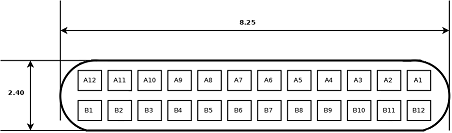
USB Type C (USB-C) Plug (Front View)
The pinout described is a full featured USB-C cable supporting USB 3.0, 3.1 and 3.2. Observant readers will spot the fact that reversing the cable will result in the same connections (just changing the A and B designations) since the pinout is reversed (Note the special cases of A6, A7, B6, B7, A5 and B5 described in the Function notes below. Note, also, that cable polarity is both detected and used for Lane routing and other functions.)
| Pin Number |
Name |
Function |
| A1 |
GND |
Ground. All grounds are tied together. |
| A2 |
TX1+ |
Transmit positive, paired with A3 to create a single Lane transmitter. The second Lane is on the B side. Cable polarity (see A5) determines Lane numbering. |
| A3 |
TX1- |
Transmit negative, paired with A2 to create a single Lane transmitter. The second Lane is on the B side. Cable polarity (see A5) determines Lane numbering. |
| A4 |
Vbus |
Power. Norminal 5V. All Vbus signals tied together. Amperage determined by connected system and may be 500 mA, 900 mA, 1.5 A or 3 A. |
| A5 |
CC |
Configuration channel. Paired with B5 to determine cable polarity and then host/device (source or sink) connection and may subsequently be used to signal power delivery options. |
| A6 |
D+ |
USB 2.0 only. |
| A7 |
D- |
USB 2.0 only. |
| A8 |
SBU1 |
Sideband used in Alterative Mode only. Not used in Full Feature USB-C mode. |
| A9 |
Vbus |
Power. Norminal 5V. All Vbus signals tied together. Amperage determined by connected system and may be 500 mA, 900 mA, 1.5 A or 3 A. |
| A10 |
RX2+ |
Receive positive, paired with A11 to create a single Lane receiver. The second Lane is on the B side. Cable polarity (see A5) determines Lane numbering. |
| A11 |
RX2- |
Receive negative, paired with A2 to create a single Lane receiver. The second Lane is on the B side. Cable polarity (see A5) determines Lane numbering. |
| A12 |
GND |
Ground. All grounds are tied together. |
| B1 |
GND |
Ground. All grounds are tied together. |
| B2 |
TX2+ |
Transmit positive, paired with B3 to create a single Lane transmitter. The second Lane is on the A side. Cable polarity (see A5) determines Lane numbering. |
| B3 |
TX2- |
Transmit negative, paired with B2 to create a single Lane transmitter. The second Lane is on the B side. Cable polarity (see A5) determines Lane numbering. |
| B4 |
Vbus |
Power. Norminal 5V. All Vbus signals tied together. Amperage determined by connected system and may be 500 mA, 900 mA, 1.5 A or 3 A. |
| B5 |
Vconn |
Paired with A5 to determine cable polarity and then host/device (source or sink) connection (where it functions as a Configuration channel pin) and subsequently used to for Electronic Cable Marking (used by USB Power Delivery (USB PD)). |
| B6 |
- |
Not connected. |
| B7 |
- |
Not connected. |
| B8 |
SBU2 |
Sideband used in alternative Mode only. Not used in Full Feature USB-C mode. |
| B9 |
Vbus |
Power. Norminal 5V. All Vbus signals tied together. Amperage determined by connected system and may be 500 mA, 900 mA, 1.5 A or 3 A. |
| B10 |
RX1+ |
Receive positive, paired with A11 to create a single Lane receiver. The second Lane is on the B side. Cable polarity (see A5) determines Lane numbering. |
| B11 |
RX1- |
Receive negative, paired with A2 to create a single Lane receiver. The second Lane is on the B side. Cable polarity (see A5) determines Lane numbering. |
| B12 |
GND |
Ground. All grounds are tied together. |
IEEE 1394 (Firewire a.k.a. i.Link)
The IEEE high speed serial connector is known as Firewire and i.Link (Japan). The IEEE 1394a-1995 specification provides up to 400 M bit/sec and uses either a 6 pin connector (PCs/Computers) or a 4 pin connector (camcorders and AV equipment). The latest specification IEEE 1394b provides up to 800 M bit/sec (but is slated for 3.2 G bit/s) and uses a 9 pin connector which may operate in 'biligual mode' (will connect to either a 4 or 6 pin IEEE 1394a connectors but needs a special converter cable) or 'beta mode' (will connect to another IEEE 1394b system).
Firewire uses the Open Host Controller Interface (OHCI)
As always the lack of freely available specifications is just a pain - leading to confusion and plain stupidity. It is a shame that the IEEE 1394 working group could not take a leaf out of the IEEE 802 group which now provides specs at no cost 12 months after their initial publication. While manufacturers typically have the resources to buy hese specs there are many developers, notably , but perhaps not exlusively, from the Open Source world, who would/could/might develop or improve drivers if specs were readily available. Sigh.
Firewire/i.Link 6 Pin Connector Assignment
This connector is usually found on PCs (Apple especially) and disk systems.
.
 |
| Pin |
Name |
Color |
Notes |
| 1 |
Power |
- |
Power (18V - 25V, 15W) |
| 2 |
GND |
- |
Ground |
| 3 |
TPB- |
- |
Pair B - |
| 4 |
TPB+ |
- |
Pair B + |
| 5 |
TPA- |
- |
Pair A - |
| 6 |
TPA+ |
- |
Pair A + |
|
Firewire/i.Link 4 Pin Connector Assignment
This very compact connector is usually found on camcorders and other digital AV equipment.
 |
| Pin |
Name |
Color |
Notes |
| 1 |
TPB- |
- |
Pair B - |
| 2 |
TPB+ |
- |
Pair B + |
| 3 |
TPA- |
- |
Pair A - |
| 4 |
TPA+ |
- |
Pair A + |
|
Firewire/i.Link 9 Pin Connector Assignment
This is the new IEEE 1394b (Firewire 800) connector which allows interconnection to older 1394a systems in 'bilingual mode'(4 or 6 pin - using an appropriate converter cable). In 'beta mode' allows connection to other 1394b systems.
Note: The power specification shown below (12 - 25V) highlights the problems of keeping definitive specifications limited to folks who are prepared to shell out filthy lucre for the privilege of reading the three lines that interest them and the confusion that arises as users legitimately try to reconcile various published specs and product notes. Various device specifications, notes and descriptions contain a variety of specific power values within the range shown below. The majority of chipset specifications use a low figure of 12V, many device descriptions (some based on the same chipsets) maintain the older maximum value of 25V. Since one of the benefits of the 1394b specification is longer cable runs on certain media types we have shown the low value as 12V since this seems to allow for increased voltage drop and consequently makes sense to us. We would be delighted to provide further information and clarification on this topic if anyone cares to update us.
 |
| Pin |
Name |
Color |
Notes |
| 1 |
TPB- |
- |
Pair B - |
| 2 |
TPB+ |
- |
Pair B + |
| 3 |
TPA- |
- |
Pair A - |
| 4 |
TPA+ |
- |
Pair A + |
| 5 |
TPA(R) |
- |
Pair A Ground Ref. |
| 6 |
VG |
- |
Power Ground |
| 7 |
SC |
- |
Status Contact (Reserved NC) |
| 8 |
VP |
- |
Power (12-25V DC, 15W) |
| 9 |
TPB(R) |
- |
Pair B Ground Ref |
|
Problems, comments, suggestions, corrections (including broken links) or something to add? Please take the time from a busy life to 'mail us' (at top of screen), the webmaster (below) or info-support at zytrax. You will have a warm inner glow for the rest of the day.


