Tech Stuff - Monitor/Display Connectors
Connection of monitors and display equipment to the PC used to be a simple topic - either CGA, EGA or VGA via D-Sub type (9 or 15 pin) connection and we were set to go (but if you had bucket loads of cash for hi-res, big screen displays it could get much more complex). Pretty simple really. Too simple to last.
Things are changing pretty quickly. The reasons behind all the changes are performance (greater screen resolution and HDTV/gaming with high frame refresh rates needs greater speed), connectivity (the display may connect to a DVD/Blue-Ray play, classic PC or a TV set-top box) and functionality (video, compressed or uncompressed, and sound may be present as well as all that dreaded content protection stuff). This all gets a bit messy. Quickly. To make matters even worse we have three - perhaps 4 - possible future connection methods which means at least 3 or 4 possible ways in which your screen may not work with your PC or AV thingie! Almost all modern monitors/displays are provided with dual or triple interfaces - a basic interface, typically VGA, and one, or more, of the newer types. So there goes the cost reduction part.
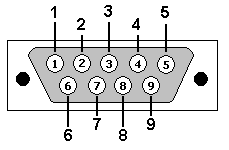
Note: The DB9 connector diagrams shown here reference the TIA/EIA - 574 standard which is not strictly correct as it defines both pin numbers and signals. In the context of this section we use it to define pin numbers only.
CGA Monitor (DB9)
For all practical puposes CGA is obsolete and is included in case you are unlucky enough to come across it.
 |
| DB9 Pin |
Name |
Function/Notes |
| 1 |
GND |
Ground |
| 2 |
GND |
Ground |
| 3 |
RED |
Red Video |
| 4 |
GREEN |
Green Video |
| 5 |
BLUE |
Blue Video |
| 6 |
Intensity |
Color Intensity |
| 7 |
RESERVED |
Reserved |
| 8 |
HSYNC |
Horizontal Sync. |
| 9 |
VSYNC |
Vertical Sync. |
|

EGA Monitor (DB9)
For all practical puposes EGA is obsolete and is included in case you are unlucky enough to come across it.
 |
| DB9 Pin |
Name |
Function/Notes |
| 1 |
GND |
Ground |
| 2 |
SRED |
Secondary Red Video |
| 3 |
PRED |
Primary Red Video |
| 4 |
PGREEN |
Primary Green Video |
| 5 |
PBLUE |
Primary Blue Video |
| 6 |
SGREEN |
Secondary Green Video |
| 7 |
SBLUE |
Secondary Blue Video |
| 8 |
HSYNC |
Horizontal Sync. |
| 9 |
VSYNC |
Vertical Sync. |
|

VGA Monitor (DB15 & DB9)
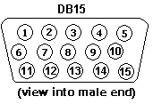
The VGA connector can use a classic DB9 connector or (more commonly today) a DB15 style connector. The female end of this connector is at the Host/PC. Interface defined by Video Electronic Standards Association (VESA). The VGA connector (15 pin) is still widely used and while it was originally used to carry a 640 x 480 pixel format it is used to carry a variety of geometries including HDTV formats. VGA is an analog standard.
DB15 Format
 |
| Pin No |
Name |
Function/Notes |
VESA DDC |
Notes |
| 1 |
RED * |
Red Video |
|
|
| 2 |
GREEN * |
Green Video |
|
|
| 3 |
BLUE * |
Blue Video |
|
|
| 4 |
ID2 |
Monitor ID Bit2 |
|
|
| 5 |
GND |
Vertical Sync. |
|
|
| 6 |
RGND |
Red Ground (Return) |
|
|
| 7 |
GGND |
Green Ground (Return) |
|
|
| 8 |
BGND |
Blue Ground (Return) |
|
|
| 9 |
NC |
No Connect |
|
|
| 10 |
SGND |
Sync Ground (Return) |
|
|
| 11 |
ID1 |
Monitor ID bit 1 |
|
|
| 12 |
ID0 |
Monitor ID bit 0 |
DDC |
Serial Data |
| 13 |
HSYNC |
Horizontal (or Composite) Sync |
|
|
| 14 |
VSYNC |
Vertical Sync |
|
|
| 15 |
NC |
No Connect |
DDC |
Serial Clock |
|
Notes:
- Older Implementations used the ID0-2 bits (Pins 12, 11 and 4) to denote limited video characteristics (mono, color and resolution). Modern Plug n' Play monitors provide enhanced data using the VESA serial DDC (Digital Data channel) interface (on Pins 12 and 15). Data sent via the DCC is in VESA defined Extended Digital Identification Data (EDID) format.

DB9 Format
 |
| DB9 Pin |
Name |
Function/Notes |
| 1 |
RED |
Red Video |
| 2 |
GREEN |
Green Video |
| 3 |
BLUE |
Blue Video |
| 4 |
HSYNC |
Horizontal Sync. |
| 5 |
VSYNC |
Vertical Sync. |
| 6 |
RGND |
Red Ground (Return) |
| 7 |
GGND |
Green Ground (Return) |
| 8 |
BGND |
Blue Ground (Return) |
| 9 |
SGND |
Sync Ground |
|

DVI (Digital-Visual Interface)
DVI is an interface for carrying uncompressed video signals. Frequently found on modern PCs, some DVD players and TV sets but rarely on laptops (its 24 - 29 pin connector is a bit too chunky) and designed as bridge between the older analog and newer digital worlds. Standardized by the Digital Display Working Group (DDWG) currently as version 1.0 DVI uniquely provides a digital and analog interface (VGA compatible signals) on the same cable. DVI was superseded by HDMI for DVD and TV applications and may be superseded by DisplayPort or Thunderbolt for PC applications due to their smaller connector size (uses the Mini DisplayPort connector).
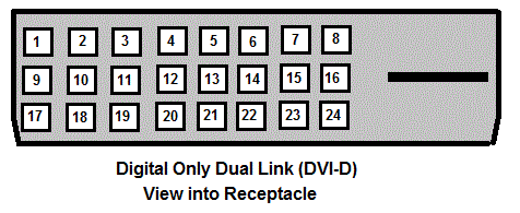
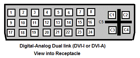
DVI comes in three flavors DVI-D (a digital only version, partly HDMI compatible), DVI-A (analog only version, partly VGA compatible) and DVI - I (a digital and analog version). The DVI-D and DVI-I versions have single and dual link flavors (the dual link essentially doubles the bandwidth). In every case the connector size is the same (10.04mm x 36.96mm max) but certain pins are not provided or not connected.
DVI mandates support of both VESA's DCC2B (Digital Data Channel - signal path) and EDID (Extended Display Identification Data - DCC data format version 1.3 and 2.0) for identification of monitor/display characteristics (Plug n' Play). DVI does not explicitly support High-bandwidth Digital Content Protection (HDCP) but HDCP does support DVI in a form frequently referred to as DVI-HDCP which was primarily used to connect DVD/TV sets until around 2007 when it was largely superseded by HDMI.
DVI uses Transition Minimized Differential Signaling (TMDS) and 8b10b encoding and supports a single Link (consisting of channels 0, 1 and 2) at clock rates up to 165 MHz (giving a maximum bandwith of 3 x 1.65 Gbit/s = 4.95 GBit/s and a maximum data rate of 4.95 x 8/10 = 3.96 GBit/s). An optional second Link (channels 3, 4 and 5) allows a theoretically unlimited clock speed. A single Link will support multiple screen resolutions including 1920 x 1080 at 60 Hz (HDTV). A dual Link will support a maximum of 2,560 x 1,600 at 60 Hz (see table of bandwidth/resolution/frequencies).
DVI suggests a maximum cable distance of 5m (~15 feet), in practice longer cables (10m+ ~30 feet+) are commercially available). Due to the compatability with VGA, DVI-A or DVI-I systems can use relatively inexpensive VGA convertors for connection to VGA only legacy monitors. Many modern monitors provide both DVI and VGA connectors to allow connection to a wide range of hosts.
Video formal is assumed to be 8-bits for Red (channels 2,5), Green (channels 1,4) and Blue (channel 0,3) (RGB) for a color depth of 3 x 8 = 24 bits. Other formats can be negotiated based on the EDID (identification) data.
Pinout for DVI-Digital (DVI-D)
 |
| Pin No. |
Name |
Function/Notes |
| 1 |
TMDS Data2- |
Channel 2 (1st link) Red |
| 2 |
TMDS Data2+ |
Channel 2 (1st link) Red |
| 3 |
TMDS Data2/4 Shield |
|
| 4 |
TMDS Data4- |
Channel 4 (2nd link) Green |
| 5 |
TMDS Data4+ |
Channel 4 (2nd link) Green |
| 6 |
DDC Clock |
Controls sending of EDID Data |
| 7 |
DDC Data |
EDID (identification) data for Plug n'Play |
| 8 |
NC |
No Connect |
| 9 |
TMDS Data1- |
Channel 1 (1st link) Green |
| 10 |
TMDS Data1+ |
Channel 1 (1st link) Green |
| 11 |
TMDS Data1/3 Shield |
|
| 12 |
TMDS Data3- |
Channel 3 (2nd link) Blue |
| 13 |
TMDS Data3+ |
Channel 3 (2nd link) Blue |
| 14 |
Power |
+ 5V |
| 15 |
Ground |
For + 5V |
| 16 |
HPD |
Hot Plug Detect. If > +2.4V Monitor EDID data available, ≤ +0.4V no monitor available |
| 17 |
TMDS Data0- |
Channel 0 (1st link) Blue |
| 18 |
TMDS Data0+ |
Channel 0 (1st link) Blue |
| 19 |
TMDS Data0/5 Shield |
|
| 20 |
TMDS Data5- |
Channel 5 (2nd link) Red |
| 21 |
TMDS Data5+ |
Channel 5 (2nd link) Red |
| 22 |
TMDS Clock Shield |
|
| 23 |
TMDS Clock+ |
|
| 24 |
TMDS Clock- |
|
|
Notes:
When a single link is provided pins 4,5 12,13 and 20,21 are not connected.
In dual link configurations odd numbered pixels are placed on link 1, even on link 2.
Link 1 consists of channels 0 - 2, link 2 consists of channels 3 - 5.
Pinout for DVI-Digital (DVI-D)
 |
| Pin No. |
Name |
Function/Notes |
| 1 |
TMDS Data2- |
Channel 2 (1st link) Red |
| 2 |
TMDS Data2+ |
Channel 2 (1st link) Red |
| 3 |
TMDS Data2/4 Shield |
|
| 4 |
TMDS Data4- |
Channel 4 (2nd link) Green |
| 5 |
TMDS Data4+ |
Channel 4 (2nd link) Green |
| 6 |
DDC Clock |
Clock controls EDID data |
| 7 |
DDC Data |
EDID (identification) data for Plug n'Play |
| 8 |
NC |
No Connect |
| 9 |
TMDS Data1- |
Channel 1 (1st link) Green |
| 10 |
TMDS Data1+ |
Channel 1 (1st link) Green |
| 11 |
TMDS Data1/3 Shield |
|
| 12 |
TMDS Data3- |
Channel 3 (2nd link) Blue |
| 13 |
TMDS Data3+ |
Channel 3 (2nd link) Blue |
| 14 |
Power |
+ 5V |
| 15 |
Ground |
For + 5V |
| 16 |
HPD |
Hot Plug Detect. If > +2.4V Monitor EDID data available, ≤ +0.4V no monitor available |
| 17 |
TMDS Data0- |
Channel 0 (1st link) Blue |
| 18 |
TMDS Data0+ |
Channel 0 (1st link) Blue |
| 19 |
TMDS Data0/5 Shield |
|
| 20 |
TMDS Data5- |
Channel 5 (2nd link) Red |
| 21 |
TMDS Data5+ |
Channel 5 (2nd link) Red |
| 22 |
TMDS Clock Shield |
|
| 23 |
TMDS Clock+ |
|
| 24 |
TMDS Clock- |
|
| C1 |
Analog Red |
|
| C2 |
Analog Green |
|
| C3 |
Analog Blue |
|
| C4 |
HYSNC |
Analog Horizontal Sync |
| C5 |
Analog Ground |
Ground return for analog Blue, Green and Red. |
|
Notes:
When only a single link is provided (DVI-I) pins 4,5 12,13 and 20,21 are not connected.
When only an analog connection (DVI-A) is provided pins 4-6, 12-16 and 19-22 are not connected.

DisplayPort Monitor/Display 20 pin connector)
DisplayPort is intended to replace DVI (and older analog standards such as VGA) for PC applications. HDMI has become the current de-facto solution for consumer appliances such as DVD/HDTV etc. The even newer Thunderbolt in turn may be viewed as an extension to DisplayPort.
DisplayPort uses a pure packet transmission scheme, carries video and audio in a variety of formats and for plug n'Play supports a range of Identification formats.
To be continued - One Day Real Soon Now™

HDMI Multi-Media 19 pin connector
High Definition Media Interface (HMDI) is used extensively in the TV and consumer appliance sectors, and is increasingly common in the PC/Laptop/Netbook (or whatever the latest marketing buzzword is these days) sector. It is defined by the HMDI Manufacturer's Group currently at Version 1.4a. All the specifications of this group - including the latest amendment 1.4a - are available at no charge from the website with the exception of the version 1.4 specification. Version 1.4, which introduced a 100MBit/s Ethernet connection, micro-connector (Type D), an auto-connector (Type E), audio-return and sundry other screen resolution levels, is only available to those who sign-up for a manufacturing license. Conspiracy theories abound. But it is strange, since at least one change (Ethernet) has an effect on cable pinout.
HDMI uses a link scheme (3 or 6 channels) similar to that defined for DVI however, at this time, only a single link (3 channel) type is in use (Type A/C). The interface speed is from 25Mhz to 340MHz (from version 1.3). When initially connected the E-EDID (VESA Extended-Enhance Device Identification Data) is read and if not recognized as HDMI then DVI (8-bit digital RGB) mode is assumed. In HDMI mode CEA CEA-861-D (sperceded by CEA-861-E on CEA website) formatting (from version 1.3) is negotiated which allows transport of uncompressed video and audio. You will pay handsomely for the privilige of reading the CEA's wondrous specifications.
The HDMI specification defines 5 connector types. The normal full-size single-link (Type A shown below), a full-size double-link (Type B, not shown, not currently used), a mini-connector (Type C, shown below), a micro-connector (Type D, not shown - defined in version 1.4) and an auto-connector (Type E, not shown - defined in version 1.4).
Cables (in the range 2 to 15m) are now supplied in one of 5 categories:
Standard - supporting 720p and 1080i HDTV resolutions.
Standard with ethernet - supporting 720p and 1080i HDTV resolutions with 100 MBit/s Ethernet.
High Speed - supporting 1080p HDTV resolutions as well as all higher resolutions covered by the HDMI specifications.
High Speed with Ethernet - supporting 1080p HDTV resolutions as well as all higher resolutions covered by the HDMI specifications and including 100 MBit/s Ethernet.
Automotive Cable - Unknown performance.
Note: HDTV standards defined a compressed video/audio format which is decoded by the receiver. When the decoded signal is sent to a display/output via an HDMI cable the video/audio signal is uncompressed.
The Consumer Electronics Control (CEC) interface is designed to control other (all) HDMI connected appliances using only one remote control from any chosen device.
HDMI natively supports and, depending on the source functionality, requires High-bandwidth Digital Content Protection (HDCP).
The TMDS transmission method is identical to DVI. Maximum throughput (340 MHz) on a high speed cable is 10.2 GBit/s (3 channels x 3.40 GBit/s) after 8b/10b transmission overhead. HDMI support 24, 30, 36 and 48 bit color depth. Basic audio capability (when present) provides stereo (2 channel) LPCM (uncompressed) at 32, 44.1 and 48KHz at sample sizes 16 - 24 bits. Additional capabilies can be provided (via E-EDID) including LPCM at 96 and 192KHz at 16 - 24 bit sample size with up to 8 channels.
Pinout for HDMI Type A Single Link Connector


|
| Pin No. |
Name |
Function/Notes |
| 1 |
TMDS Data2+ |
Channel 2 (1st link) |
| 2 |
TMDS Data2 Shield |
Channel 2 (1st link) Sheild |
| 3 |
TMDS Data2- |
Channel 2 (1st link) |
| 4 |
TMDS Data1+ |
Channel 1 (1st link) |
| 5 |
TMDS Data1 Shield |
Channel 1 (1st link) |
| 6 |
TMDS Data1- |
Channel 1 (1st link) |
| 7 |
TMDS Data0+ |
Channel 0 (1st link) |
| 8 |
TMDS Data0 Shield |
Channel 0 (1st link) |
| 9 |
TMDS Data1- |
Channel 0 (1st link) |
| 10 |
TMDS Clock+ |
Clock rates can vary from a minimum of 25 Mhz to a maximum of 340 MHz. |
| 11 |
TMDS Clock Shield |
|
| 12 |
TMDS Clock- |
|
| 13 |
CEC |
Consumer Electronics Control commands (remote control). Any cascaded HDMI connections interlink CEC connection. |
| 14 |
Reserved |
N.C. on version 1.3. Version 1.4? |
| 15 |
SCL |
DDC Clock for transmission of E-EDID data |
| 16 |
SDA |
DDC data (E-EDID) identification for Plug n'Play |
| 17 |
DCC/CEC Ground |
|
| 18 |
+5V Power. Source must provide 55mA. Sink allowed max of 50 mA (10 mA when powered) |
|
| 19 |
Hot Plug Detect |
If > +2.4V Monitor E-EDID data available, ≤ +0.4V no monitor available |
|
Notes:
While the pin geometry of Type A and Type C connectors is different, pinout numbering is identical. For those of a visually literal disposition it may be worth pointing out that a Type C connector is substantially smaller than a Type A connector!
As a consequence of the lack of a freely available HDMI 1.4 spec. the 100mBit/s Ethernet feature defined in that specification is not described in the pinout section. Sigh. Please also note that 5 cable types (described in the text) are defined in the 1.4 specification. Cables purchased prior to the new 1.4 standard will work with newer 1.4 devices but will obviously not support newer functionality which require additional pinout capability, for example, 100 MBit/s Ethernet. In additional 1.4 functionality, such as, increased resolutions or 3D support, require both ends of the connection to have equivalent (1.4) functionality/firmware.

Thunderbolt (20 pin connector)
placeholder
Real Soon Now™. Or rather, when the spirit moves us.

Problems, comments, suggestions, corrections (including broken links) or something to add? Please take the time from a busy life to 'mail us' (at top of screen), the webmaster (below) or info-support at zytrax. You will have a warm inner glow for the rest of the day.


